
Thread Support for Flipper Zero, Part 3: Interfacing, Thread Networks and Data Sets

Introduction
This is the third part in the series. I will build on the previous posts in this one, so I highly recommend starting with them first. Here are the links to part one and part two.
In part two I explained how to set up the environment and build a working sample firmware application. This section will explain how to setup communication between Flipper Zero’s UART pins and the nRF 52840 dongle’s UART pins.
My research focuses on enhancing CUJO AI’s security solutions to protect home routers and consumers from potential attacks. I am particularly concerned about the risks associated with Thread and the new attack surfaces it introduces. Specifically, I worry about the threats from insecure or malicious IoT devices, such as IP cameras, smart locks, and smart doorbells. My goal is to anticipate potential issues that may arise in IoT environments utilizing Thread and to identify the actions an attacker might take.
My work focuses on detecting and protecting against emerging threats associated with Thread networks. I aimed to initiate TCP and UDP connections from the Thread network and track their routing. However, I discovered that no currently available devices can achieve this without building and coding a new firmware image for specific radios.
By leveraging Matter, I can ensure interoperability and ease of use across various devices and platforms. By default, all the ecosystems are secretive about keys and configuration options. Now there is the official way of connecting multiple Thread networks, for example, Amazon Alexa’s mobile app is the only one with manual Thread network key input options.
At the end of this post, I will open-source a tool to conduct fundamental Thread network discoveries and network inspection.
Interface with nRF Soc via UART
As described in the last post, we first need to modify the dongle to support an external power source, then connect the following four pins :
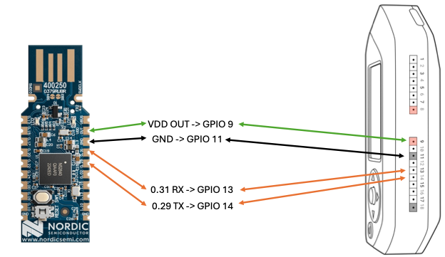
The next step is to configure our pins via device tree. This DT definition will configure the SoC’s GPIO pins according to the upper image.
UART_TX is the 0.29
UART_RX is the 0.31
Add a new file connectedhomeip/examples/lighting-app/nrfconnect/uart-pinctrl.dtsi
&pinctrl {
uart1_default: uart1_default {
    group1 {
        psels = <NRF_PSEL(UART_TX, 0, 29)>,
            <NRF_PSEL(UART_RTS, 0, 0xFFFFFFFF)>;//0xFFFFFFFF not connected UART_PIN_DISCONNECTED
    };
    group2 {
        psels = <NRF_PSEL(UART_RX, 0, 31)>,
             <NRF_PSEL(UART_CTS, 0, 0xFFFFFFFF)>; //0xFFFFFFFF not connected UART_PIN_DISCONNECTED
        bias-pull-up;
    };
};

uart1_sleep: uart1_sleep {
    group1 {
         psels = <NRF_PSEL(UART_TX, 0, 29)>,
            <NRF_PSEL(UART_RX, 0, 31)>,
            <NRF_PSEL(UART_RTS, 0, 0xFFFFFFFF)>,
            <NRF_PSEL(UART_CTS, 0, 0xFFFFFFFF)>;
            low-power-enable;
    };
};
};
We will have to include the uart-pinctrl.dtsi and configure the SoC to use the pins as uart0 for shell.
connectedhomeip/examples/lighting-app/nrfconnect/usb-dongle.overlay
/*
 * Copyright (c) 2021 Nordic Semiconductor ASA
 *
 * SPDX-License-Identifier: LicenseRef-Nordic-5-Clause
 */
#include "uart-pinctrl.dtsi"
 / {
  chosen {
    zephyr,shell-uart = &uart0;
  };
};

&uart0 {
  compatible = "nordic,nrf-uart";
  /* default state */
  /* default state */
  pinctrl-0 = <&uart1_default>;
  /* sleep state (only applicable if CONFIG_PM_DEVICE=y) */
  pinctrl-1 = <&uart1_sleep>;
  /* state assigned to each pinctrl-N property by index */
  pinctrl-names = "default", "sleep";
};

/delete-node/ &slot1_partition;

&storage_partition {
  reg = <0xf7000 0x9000>;
};
Overwrite the content of connectedhomeip/examples/lighting-app/nrfconnect/boards/nrf52840dongle_nrf52840.overlay
&uart0 {
    status = "okay";
    hw-flow-control;
};

/ {
    chosen {
        zephyr,entropy = &rng;
    };
};
connectedhomeip/examples/lighting-app/nrfconnect/ot_uart_shell.overlay
CONFIG_THREAD_NAME=n
CONFIG_OPENTHREAD_SHELL=y
CONFIG_SHELL=y
CONFIG_CHIP=y
CONFIG_CHIP_LIB_SHELL=y
CONFIG_SHELL_CMD_BUFF_SIZE=384
NOTE: CONFIG_SHELL_CMD_BUFF_SIZE is important. Otherwise, the UART terminal will not support long enough lines to set a dataset later. The default 128 characters is less than 213, which is my test dataset size.
With these four files, our build command will get a bit more complicated
west build --pristine --build-dir ./build --board nrf52840dongle/nrf52840 --sysbuild -- -DOT_BOOTLOADER=USB -DOVERLAY_CONFIG:STRING=ot_uart_shell.overlay -DDTC_OVERLAY_FILE:STRING="usb-dongle.overlay;boards/nrf52840dongle_nrf52840.overlay" | tee build.log
The parameters are the following:
- –board nrf52840dongle/nrf52840: Targeting the Nordic nRF52840 Dongle.
- –sysbuild: Building both the MCU bootloader and application.
- -DOT_BOOTLOADER=USB: Enable USB bootloader.
- -DOVERLAY_CONFIG: Applies the ot_uart_shell.overlay for OpenThread and UART shell configurations.
- -DDTC_OVERLAY_FILE: Applies multiple Device Tree overlays for our UART and board-specific configurations.
Flash the firmware as described in part two.
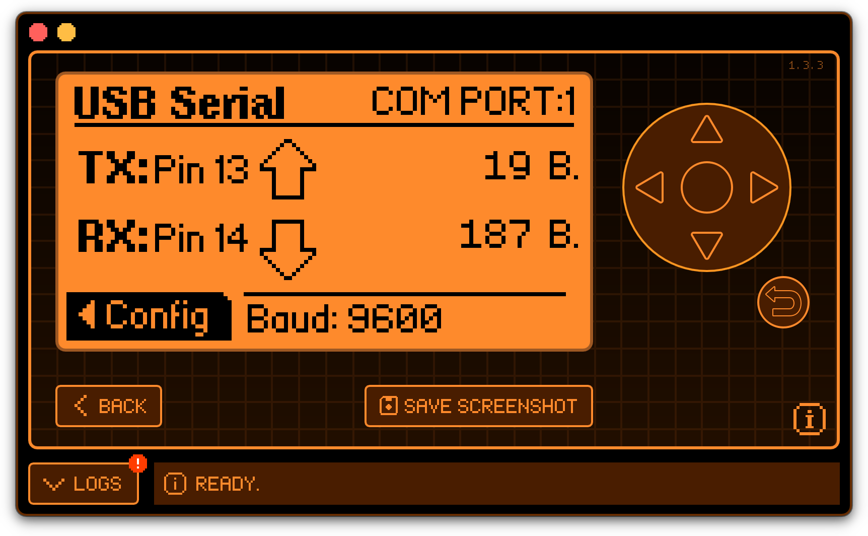
Use Flipper Zero’s USB-UART Bridge app, configure it for USB Channel 1
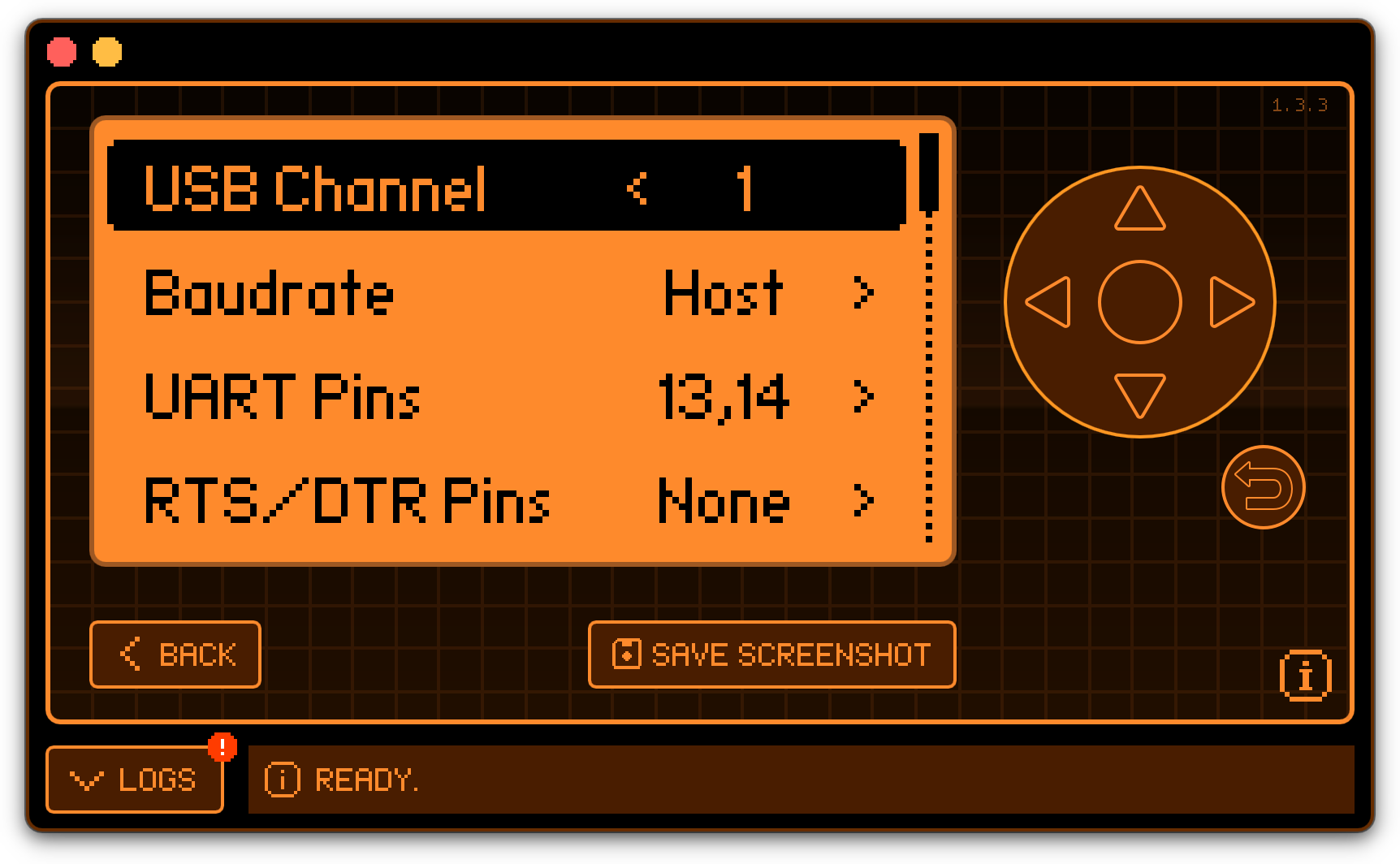
Then connect Flipper Zero to your computer via USB-C and connect to the second (or in this case, third) tty port, and access the “matter” and “ot” help menu:
tio /dev/tty.usbmodemflip_Ox0gal3
[16:03:49.988] tio 3.9
[16:03:49.989] Press ctrl-t q to quit
[16:03:49.990] Connected to /dev/tty.usbmodemflip_Ox0gal3

uart:~$ help

Available commands:
help
matter
ot
uart:~$
At this point, we created a UART bridge between the nRF SoC and the computer’s USB-C port with Flipper Zero acting as a bridge.
We can use the serial access to scan for OpenThread networks.
uart:~$ ot scan
| PAN | MAC Address | Ch | dBm | LQI |
+------+------------------+----+-----+-----+
| 9749 | ee9afe59da7e515e | 11 | -60 | 132 |
| e948 | b607cebacff14b2c | 25 | -60 | 136 |
| e948 | 767d9c5ac6dfb1bd | 25 | -33 | 240 |
Done
Thread Networks
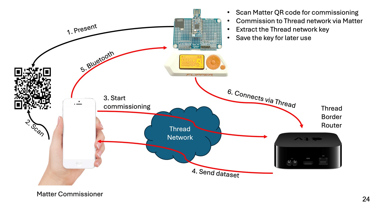
How Simple Thread Connection Works
Connecting to an existing Thread network involves a few steps. Here’s a simplified overview of the process and the corresponding concepts:
Joining an Existing Thread Network
To connect a new device to an existing Thread network, follow these steps:
- Power the Device On: Ensure the device you want to connect is powered on and within the range of the Thread network.
- Initiate the Joining Process: The device will typically have a method for initiating the joining process, such as pressing a button or using a mobile app. In our case, this app is the Flipper Zero script.
- Authenticate and Secure the Connection: The device will need to authenticate itself to the network. This usually involves entering a network credential, such as a passphrase or using a QR code provided by the network administrator.
- Obtain Network Parameters: The device will receive network parameters, including the network name, channel, and security credentials.
- Join the Network: Once authenticated, the device will join the network and communicate with other devices.
Options for Connecting to an Existing Thread Network
- Using a Mobile App: Many Thread-enabled devices can be connected using a mobile app provided by the device manufacturer. The app will guide you through connecting the device to the network.
- Using a QR Code: Some devices come with a QR code that can be scanned to configure the device with the necessary network credentials automatically.
- Manual Configuration: Sometimes, you may need to manually enter the network credentials (e.g., network name, passphrase) into the device’s configuration interface.
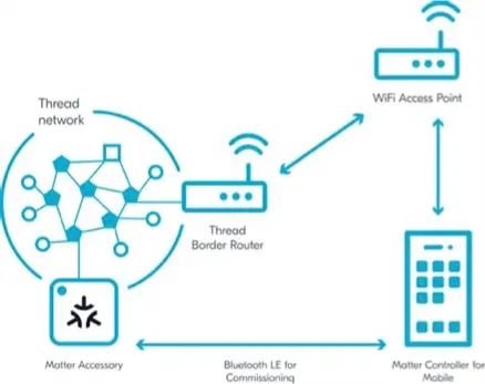
- Commissioning via a Border Router: If the network has a Border Router, it can facilitate commissioning by providing the new device with the necessary network parameters.
- Commissioning via Matter: If the network has a Matter controller, we can facilitate the commissioning process using the method described in part 2.
Connecting a device to an existing Thread network is designed to be straightforward and secure. By following the steps outlined above and using the available options, you can easily add new devices to your Thread network.
Another Way to Connect
- Use a leaked joiner password (it needs an open joiner window on the network, initiated from inside to be usable)
- Use Matter for initial connection and leak, or save the network key
- Manual configuration via CLI accessible through the UART bridge
- Use a leaked dataset
- Use a known network key
What Can We Do via the UART CLI Access?
It depends on your firmware build parameters, but the complete list is accessible on the website.
uart:~$ ot help
bbr
bufferinfo
ccathreshold
channel
child
childip
childmax
childrouterlinks
childsupervision
childtimeout
coap
contextreusedelay
counters
dataset
debug
delaytimermin
detach
deviceprops
discover
dns
domainname
dua
eidcache
eui64
extaddr
extpanid
factoryreset
fem
ifconfig
instanceid
ipaddr
ipmaddr
joinerport
keysequence
leaderdata
leaderweight
log
mac
mode
multiradio
neighbor
netdata
netstat
networkdiagnostic
networkidtimeout
networkkey
networkkeyref
networkname
nexthop
panid
parent
parentpriority
partitionid
ping
platform
pollperiod
preferrouterid
promiscuous
pskc
pskcref
rcp
region
releaserouterid
reset
rloc16
router
routerdowngradethreshold
routereligible
routerselectionjitter
routerupgradethreshold
scan
singleton
srp
state
thread
txpower
udp
unsecureport
uptime
vendor
version
Done
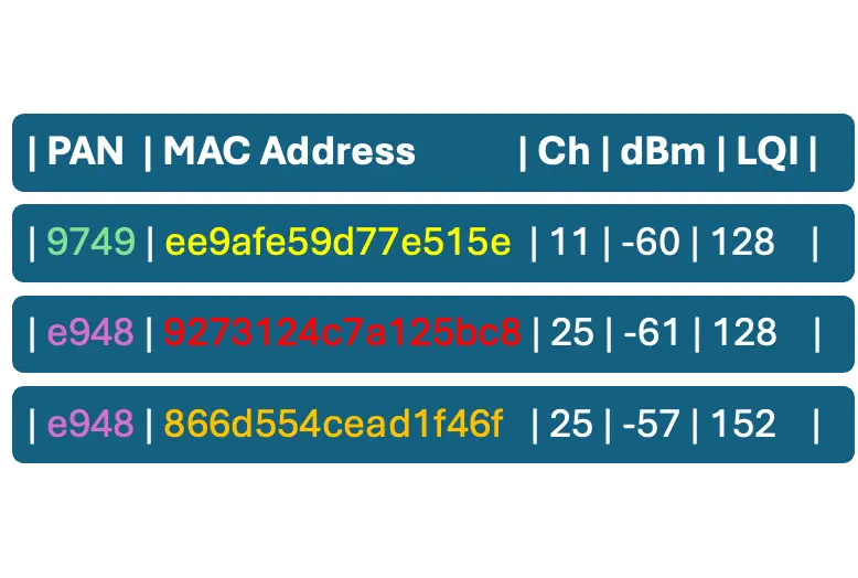
We have used the “ot scan” command earlier to perform an active IEEE 802.15.4 scan. If no channel is specified, the scan covers all channels; otherwise, the scan covers only the channel specified.
The IEEE 802.15.4 primitive scan sends a beacon via the physical layer; details can be found on otLinkActiveScan.
A sample scan result color-coded for better clarification:
We have another command, “ot discover” to perform an MLE Discovery operation. Mesh Link Establishment (MLE) protocol to configure links and disseminate information about the network to Thread devices.
https://github.com/openthread/openthread/blob/main/src/core/thread/discover_scanner.cpp# L54
Send MeshCoP Discovery (Layer 3) uart# ot discover -> otThreadDiscover
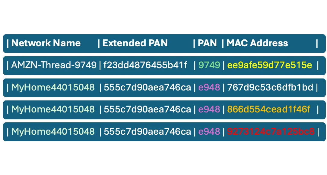
These commands require no previous knowledge about the network; it’s back to the good old days for warwalking/wardriving0. Just ask for the PAN Channel and Network name.
What’s a Thread Data Set, and Why It’s Interesting
Thread Dataset is a structured collection of configuration parameters that define the operational settings of a Thread network.
When a Thread device (like a Border Router or Leader) creates a new network, it generates an Active Dataset containing all the necessary configuration parameters (e.g., channel, PAN ID, network key). This dataset is then first stored locally on the device and shared with other devices joining the network.
The Active Dataset is propagated across the mesh so that all devices operate with the same configuration. This ensures consistent communication settings and secure and synchronized operation. When a new device wants to join the network, it receives the Active Dataset during commissioning (via a Commissioner or Joiner Router), and the dataset tells the device how to configure its radio, security, and addressing.
Thread devices store datasets in non-volatile memory. To update the network (e.g., change channel or security settings), a Pending Dataset is created and distributed. It includes a delay timer and a timestamp. Once the timer expires, the Pending Dataset becomes the new Active Dataset. This allows for coordinated, non-disruptive updates across the network.
Quote from the reference documentation:
“WARNING – Restrictions for production use!
The CLI commands to write or change the Active and Pending Operational Datasets may allow setting invalid parameters, or invalid combinations of parameters, for testing purposes. These CLI commands can only be used:
- To configure network parameters for the first device in a newly created Thread network.
- For testing (not applicable to production devices).
In production Thread networks, the correct method to write or change Operational Datasets is through a Commissioner that performs commissioning. Production devices that are not an active Commissioner and are part of a Thread network MUST NOT modify the Operational Datasets in any way.“
But we are going to use it to test production networks, so it’s okay.
A Thread network dataset refers to a structured collection of configuration parameters used to define and manage a Thread network.
There are two main types of data sets in a Thread network:
- Active Operational Dataset:
This contains the current configuration settings a Thread device uses to join and operate within a network. It includes parameters like:- Network name
- Network key
- Channel
- PAN ID (Personal Area Network ID)
- Extended PAN ID
- Security policy
- Mesh local prefix
- Pending Operational Dataset:
This is used to schedule future changes to the network configuration. It allows updates to be applied at a specific time, ensuring a smooth transition without disrupting the network.
We have two crucial commands here to handle and print the networks dataset.
Print the current active dataset:
uart:~$ ot dataset active -x 0e080000000000010000000300001235060004001fffe00208a1fce8946f2f9b1d0708fd505ff6fd1b325b0510e67446d4e450ad76cd3ad5472530d410030f4f70656e5468726561642d656539370102ee97041042743e8b67c06353cd038520a0ab8b7f0c0402a0f7f8
We can set a new active dataset, great for testing
ot dataset set active 0e080000000000010000000300001235060004001fffe00208a1fce8946f2f9b1d0708fd505ff6fd1b325b0510e67446d4e450ad76cd3ad5472530d410030f4f70656e5468726561642d656539370102ee97041042743e8b67c06353cd038520a0ab8b7f0c0402a0f7f8
Done
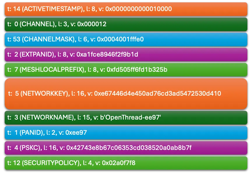
And we can print the active dataset in a human-readable version:
uart:~$ ot dataset active
Active Timestamp: 1
Channel: 18
Channel Mask: 0x07fff800
Ext PAN ID: a1fce8946f2f9b1d
Mesh Local Prefix: fd50:5ff6:fd1b:325b::/64
Network Key: e67446d4e450ad76cd3ad5472530d410
Network Name: OpenThread-ee97
PAN ID: 0xee97
PSKc: 42743e8b67c06353cd038520a0ab8b7f
Security Policy: 672 onrc 0
Done
How to Parse the Data Set?
$ python3 tlv-parser.py
Can We Find the Default Thread Network Keys?

First, look to find some shared keys on GitHub.
https://github.com/search?q=%22dataset+set+active+0%22&type=code
I extracted the following unique network key from public datasets on GitHub:
b3914792d44f45b6c7d76eb9306eec94
f366cec7a446bab978d90d27abe38f23
15f62338e7c77a9b19dad9f3165f9405
c6d2c28a700176d8cd8e7d49a64395f8
62b2442a928d9ea3b947a1618fc4085a
8e2104f183e698da87e96efc1e45aa51
112233445566778899aabbccddeeff00
e67446d4e450ad76cd3ad5472530d410
1d81689e4c0a32f3b4aa112994d29692
00112233445566778899aabbccddeeff
636f718d5b4a61d4672490104fc21ab4
5c9a2475b25dbba261b9d557a9a7fa33
fe0458f7db96354eaa6041b880ea9c0f
Default Open Thread from https://github.com/simenkid/ot-ctl/blob/main/index.js
11112233445566778899DEAD1111DEAD
1234c0de7ab51234c0de7ab51234c0de
00112233445566778899aabbccddeeff
A sample from GL-INET https://docs.gl-inet.com/iot/en/thread_board_router/gls200/openthread_border_router_codelabs/
e67446d4e450ad76cd3ad5472530d410
We can test our network for known and default network keys quite easily.
What’s the Minimum Distance to Connect to a Network?
Based on some research, the Thread signal range in buildings is between 15 m and 50 m, but with proper antennas and boosted signal strength, it might reach 100 m.
Let’s assume we are within the range of one or more Thread networks.
We can use the standard Thread API to fine-tune the radio transmit power:
- otPlatRadioSetChannelTargetPower (channel, power) sets the target transmit power (in dBm) for a specific channel
- otPlatRadioSetTransmitPower(), which sets the power for all channels uniformly
The default power is +0 dBm, and based on the SoC documentation, we can safely increase it to +8 dBm.
The relationship between transmit power and range is non-linear and affected by environment (indoor vs. outdoor), antenna gain, and receiver sensitivity.
However, a rough estimate is that the indoor range is 30% of the outdoor range.
|
Power (dBm) |
Power (mW) |
Outdoor Range (m) |
Indoor RRange(m) | |
|
+0 |
1 |
50 |
15 | |
|
+4 |
2.51 |
70 |
21 | |
|
+10 |
10 |
150 |
45 | |
|
+20 |
100 |
500 |
150 | |
So, assume that warwalking is theoretically possible, as the signal is expected to penetrate building walls.
And what’s needed to connect to the network?
|
Value |
Source |
|
PAN ID |
ot scan |
|
Channel ID |
ot scan |
|
Network Name |
ot discover and it correlates via MAC and PAN ID |
|
Network Key |
Leak or brute force |
Why This Is Useful
At this point, we created a battery-supported mobile Thread radio with slightly increased range and scanning and connection features. This radio can be used to check your own network, validate the radio range, and accessibility. The next step is to create a Flipper Zero app and store the collected information.
Stay tuned for the fourth part in the series and follow CUJO AI Labs on BlueSky: @cujoailabs.bsky.social