Hardware Hacking 101: E01 I2C Sniffing, How to Listen to Your Arduino’s I2C Bus

Introduction
Hardware hacking is one of those topics that I always had a great interest in, but almost always lacked the free time and equipment to fiddle with.
You may think that it has a much more perpendicular learning curve than programing or any other security-related research, so, hopefully, this article can disperse those thoughts and it can help to start your own research.
This is the initial post of a series where I will demonstrate and explain some of the fundamentals of hardware hacking recon and internals of wire protocols. I assume the reader has basic programming and electronics skills.
Motivation
I won’t describe the tedious job of building a lab, but would like to provide a short list of tools and devices that I use. Buying all of these should not cost you more than 200USD.
Here’s the equipment you should have:
- A multimeter. I recommend one with an auto-ranging feature and a replaceable fuse (pretty cheap to fix if you manage to fry your device).
- A good soldering iron. Make sure to get one with temperature controls and replaceable tips. It’s best to avoid cheap uncontrolled irons. As for the solder, use a 0.5 mm spool.
- Hand tools, such as a screwdriver, wire cutter and nose pliers.
- Last but not least, you’ll need some programmable single-board microcontrollers. There are dozens of Arduino as well as cheap single-board RasperyPi models on the market.
- You will also need a breadboard, resistors, jumpers, capacitors, and LEDs. Since it’s hard to know exactly what you might need, I recommend getting a starter kit from a vendor, for example, an Arduino Starter Kit, and extending it on demand.
You will also need some specific tools for hardware hacking:
- a desoldering pump
- a flux pen
- pry tools
- helping hands
And some tools for interfacing, which is where we might easily go over the original 200USD budget.
- a USB TTL adapter
- a logic analyzer, a tool used to monitor and decode a wide range of digital signals.
- an oscilloscope, a multimeter on steroids; it can measure and display at least one value over time.
The First Step is Always the Hardest
Let’s start by setting up a simple hardware hacking experiment and capture I2C traffic directly from the wire. For experimenting and learning, we should use a controlled and familiar environment.
I2C protocol and components
I2C or (eye-squared-C) is a synchronous, multi-master, multi-slave, packet-switched, single-ended, serial communication bus invented in 1982 by Philips Semiconductors. Its good for our use case, as it has the simple two-wire SDA (Serial Data line) and SDC (Serial clock line) implementation.
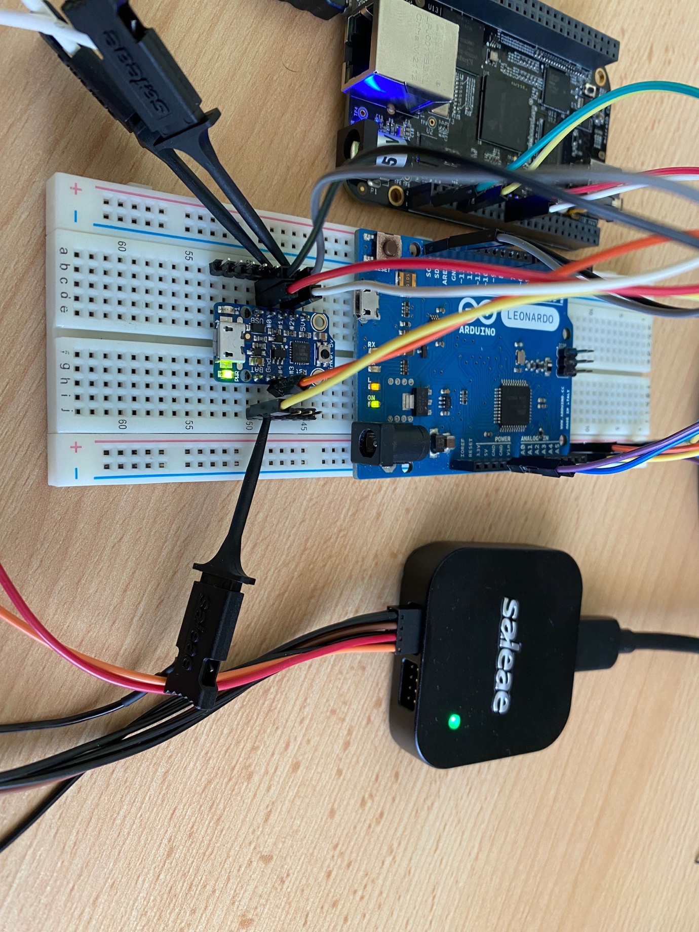
A typical setup looks like this:
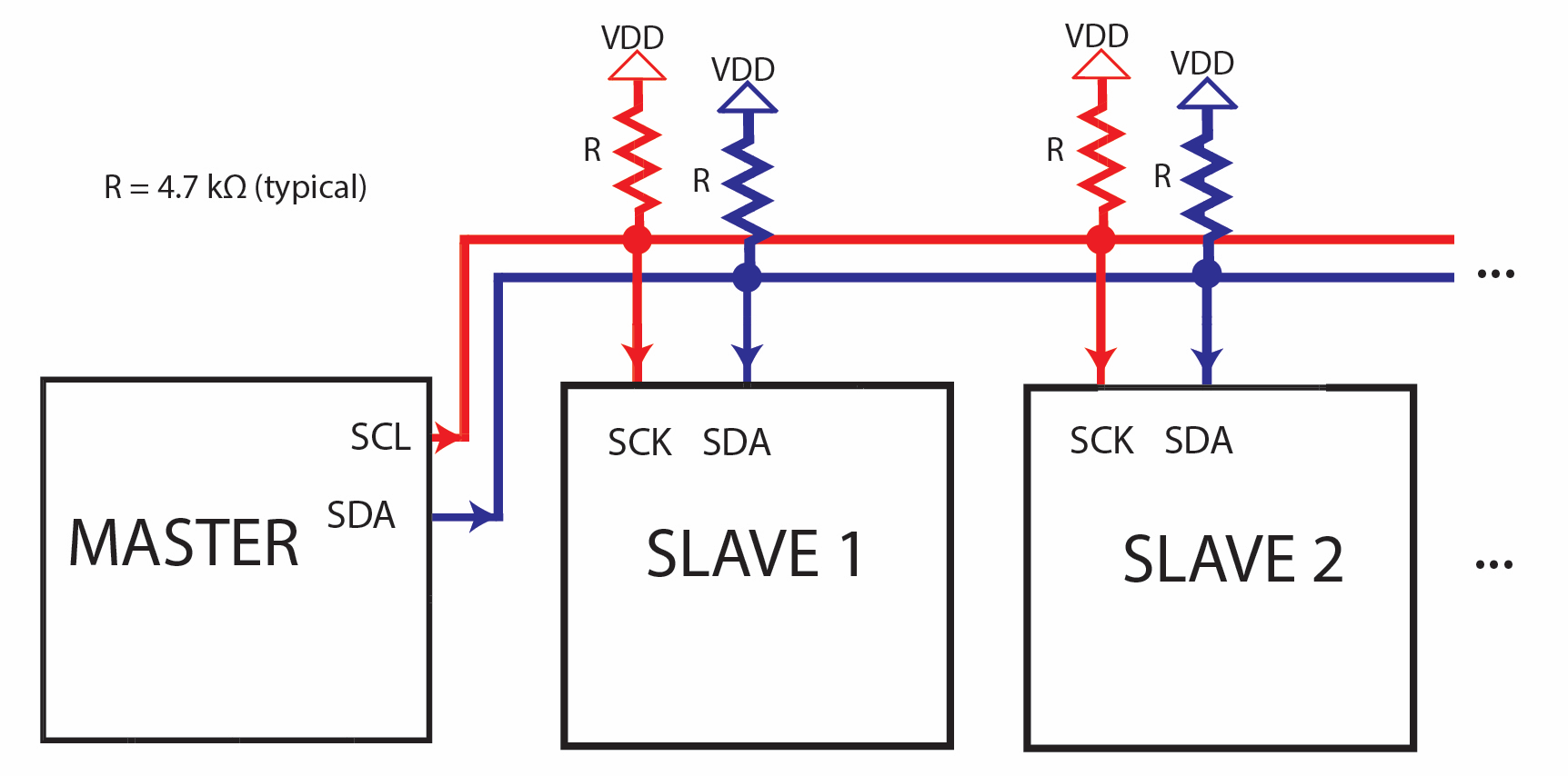
This design supports +5v and +3.3V. I will use the 3.3 V version with BeagleBone Black as the master and an Arduino and a Trinket as slaves.
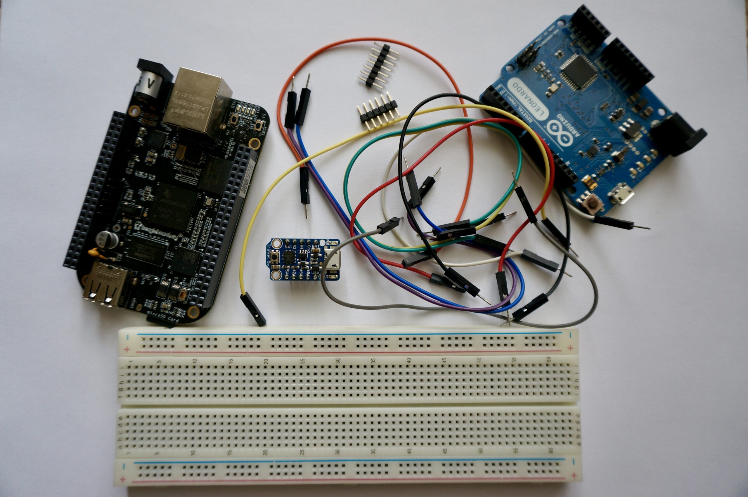
Components used in this experiment:
- BeagleBoard.org – black
- Adafruit Trinket – Mini Microcontroller – 5V Logic
- Arduino – ArduinoBoardLeonardo
- Saleae Logic 8 & BitMagic Basic Logic Analyzer
- Some jumper wire
- A solderless breadboard
I want to get from here:
To here:
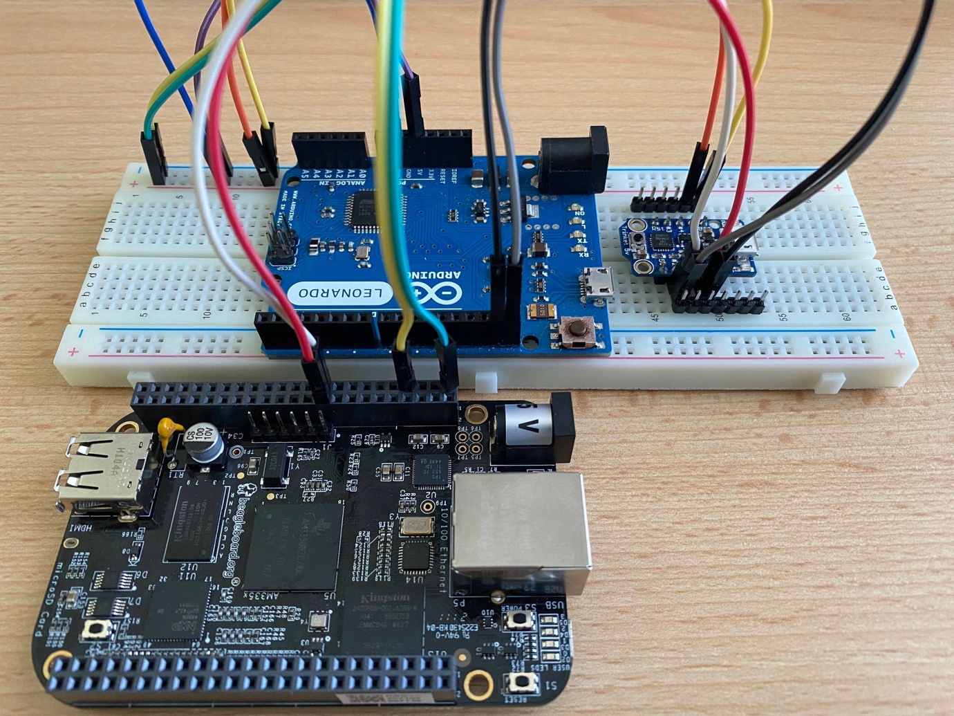
And get those LEDs blinking
 |
 |
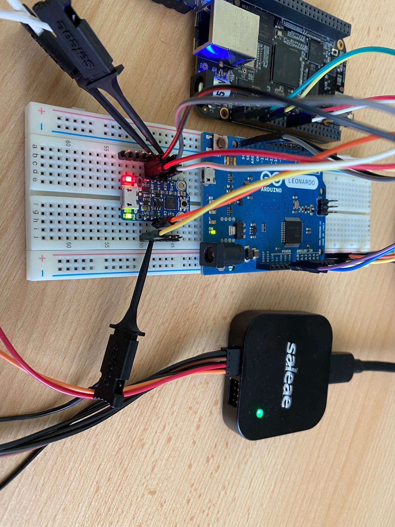
And capture the I2C message from the wire:
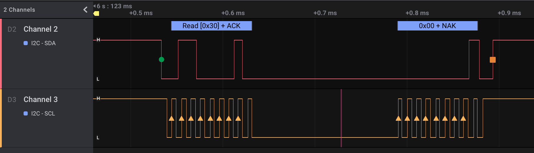
1 2 3 4 5 6 7 8 9 10 11 12 13 14 15 16 |
write to 0x30 ack data: 0x00 read to 0x30 ack data: 0x00 write to 0x30 ack data: 0x01 read to 0x30 ack data: 0x00 write to 0x30 ack data: 0x02 read to 0x30 ack data: 0x01 write to 0x30 ack data: 0x03 read to 0x30 ack data: 0x00 write to 0x34 ack data: 0x00 read to 0x34 ack data: 0x00 write to 0x34 ack data: 0x01 read to 0x34 ack data: 0x00 write to 0x34 ack data: 0x02 read to 0x34 ack data: 0x01 write to 0x34 ack data: 0x03 read to 0x34 ack data: 0x00 |
The Setup of My Lab Environment
Software
| Software component | Description |
| Arduino IDE | Integrated development environment with support for Arduino and compatible boards. |
| TinyWire/TinyWireS at rollback · rambo/TinyWire | A modified TinyWire lib version that supports I2C slave functions on ATtiny85 based devices. |
| Adafruit-PlatformDetect | Adafruit latest python support library. |
Arduino IDE Setup
A full description of the Adafruit Arduino IDE setup is available here.
The short version: add the following URL https://adafruit.github.io/arduino-board-index/package_adafruit_index.json as an Additional Boards Manager URL on the preference page.
USB cables
I own a huge number of micro USB, mini USB, and other USB cables. But almost half of them are worthless because the data cables are either missing (i.e. they are only for charging) or torn. All of my short cables turned out to be only suitable for charging.
I also suffered some failures because of missing or lousy insulation, as well as some of my USB hubs not cooperating for flashing Trinket firmware.
Test your cables and hubs one by one to find out which are the most suitable to work with.
Arduino Leonardo
I initially started writing my sample codes on a Trinket described in the next section, but quickly realized that it’s too limited to be used as a learning device. Thankfully, I found a spare Arduino Leonardo in my drawer. Leonardo has significant advantages with its more complete USB serial support and it’s also less picky about the USB cables than my Trinket. All the libraries are working as expected on this board.
My app on Leonardo acts as an I2C slave listening on 0x30. Whenever it gets the number 2, it switches the LED on, otherwise it switches it off. If the I2C master asks, the board can tell the state of the LED.
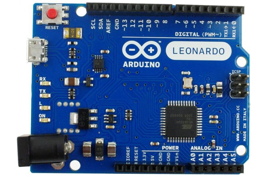
The wiring is also easy, as the SDA and SCL pins are clearly indicated on the board.
1 2 3 4 5 6 7 8 9 10 11 12 13 14 15 16 17 18 19 20 21 22 23 24 25 26 27 28 29 30 31 32 33 34 35 36 37 38 39 40 41 42 43 44 45 46 47 48 49 50 51 52 53 54 55 56 57 58 59 60 61 62 63 64 65 66 67 68 69 70 71 72 73 74 75 76 77 78 |
/// Arduino Leonardo #include <Wire.h> int LED = 13; // Leonardo onboard LED int valueReceived; int isOn = 0; // Off = 0 On = 1 int I2C_ADDR = 0x30; #define DEBUG 0 #ifdef DEBUG #define DEBUG_PRINT(x) Serial.println (x) #else #define DEBUG_BLINK(x) #endif void setup() { //Set up serial output baud number Serial.begin(9600); // Define the LED pin as Output pinMode (LED, OUTPUT); // Start the I2C Bus as Slave on address 0x30 Wire.begin(I2C_ADDR); // Attach a function to trigger when something is received. Wire.onReceive(receiveEvent); // Attach a function to trigger when something is requested Wire.onRequest(requestEvent); } void receiveEvent(bool bytes) { DEBUG_PRINT("-> read from master "); if (Wire.available() <= 0) { Serial.println("--> NOP "); } //Read one value from the I2C valueReceived = Wire.read(); DEBUG_PRINT(valueReceived); //If the value received was 2 turn the LED on, otherwise turn it off if (valueReceived == 2) { DEBUG_PRINT("-> SWITCH LED ON"); isOn = 1; } else { DEBUG_PRINT("-> SWITCH LED OFF"); isOn = 0; } } // function that executes whenever data is requested by master // this function is registered as an event, see setup() void requestEvent() { //Tell the master whether the LED is on or not DEBUG_PRINT("-> Send to master"); Wire.write(isOn); DEBUG_PRINT(isOn); if (isOn == 1) { DEBUG_PRINT("-> LED is on"); } else { DEBUG_PRINT("-> LED is off"); } } void loop() { //Turn on or off the LED based on the master's input if (isOn) { digitalWrite(LED, HIGH); } else { digitalWrite(LED, LOW); } //DEBUG_PRINT("loop"); delay(1000); } |
Trinket @I2C 0x34
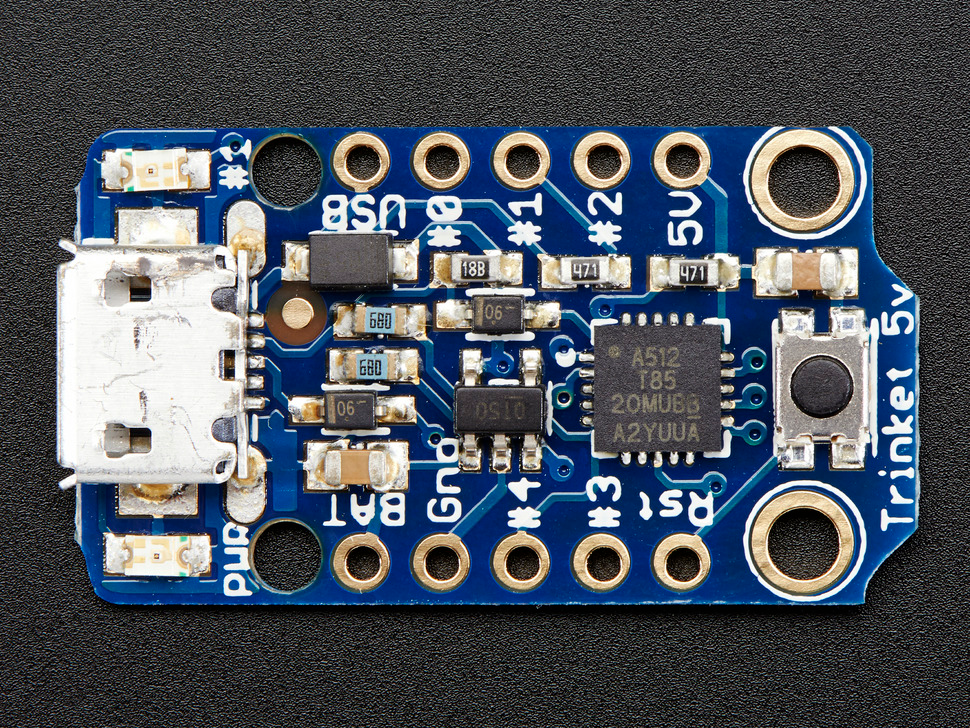
When I initially started working on the Trinket code, I thought that I was using the standard Arduino – Wire lib. But I quickly realized that something was odd when my first build failed with strange missing functions and missing parameter messages.
When I enabled the Adafruit board support described in the section on the Arduino IDE setup, it also installed a device-specific and horribly incomplete Wire lib. Namely, the Trinket’s I2C lib TinyWireM/README.md at master · adafruit/TinyWireM .
While the standard lib support is somewhat complete, the TinyWireM lacks the I2C slave support altogether. So technically, you can only use the Trinket as an I2C master. Fortunately, someone ran into this pitfall earlier and created the GitHub – rambo/TinyWire: My modifications to TinyWire Arduino libs lib.
The TinyWireS lib was almost perfect, it lacked only the proper ATtiny85 pinout support data.
Trinket itself lacks serial port support, so you cannot really debug your code or print any message to your console. It’s also a bit cumbersome to use your only LED for debugging as well as the target function.
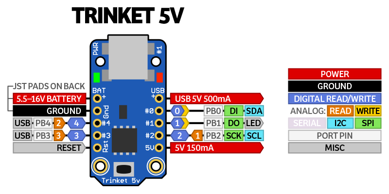
After some investigation and experimenting, I was able to build a working I2C app on my little Trinket.
My app is hard wired to use the address 0x34 and it sets the integrated LED pin to high and switches it on if it receives the number 2 via the I2C channel.
1 2 3 4 5 6 7 8 9 10 11 12 13 14 15 16 17 18 19 20 21 22 23 24 25 26 27 28 29 30 31 32 33 34 35 36 37 38 39 40 41 42 43 44 45 46 47 48 49 50 51 52 53 54 55 56 57 58 59 60 61 62 63 64 65 66 67 68 69 70 71 72 73 74 75 76 77 78 79 80 81 82 83 84 85 86 |
/* add TinyWireS as the Adafruit wire lib lacks the I2C slave implementation https://github.com/rambo/TinyWire/tree/rollback/TinyWireS // usiTwiSlave.c add the proper support to Adafruit Trinket #if defined(__AVR_ATtiny85__) #define DDR_USI DDRB #define PORT_USI PORTB #define PIN_USI PINB #define PORT_USI_SDA PORTB0 #define PORT_USI_SCL PORTB2 #define PIN_USI_SDA PINB0 #define PIN_USI_SCL PINB2 #define USI_START_COND_INT USISIF #define USI_START_VECTOR USI_START_vect #define USI_OVERFLOW_VECTOR USI_OVF_vect #endif */ #include <TinyWireS.h> #define I2C_ADDR 0x34 // 7 bit I2C address for DS1621 temperature sensor #define LED1_PIN 1 // ATtiny Pin 1 #define DEBUG 0 #ifdef DEBUG // Trinket lacks serial support so we use the LED to debug blinks void blink(int millisec) { digitalWrite(LED1_PIN, HIGH); delay(millisec); digitalWrite(LED1_PIN, LOW); } #define DEBUG_BLINK(x) blink (x) #else #define DEBUG_BLINK(x) #endif int valueReceived; int isOn = 0; // Off = 0 On = 1 void setup() { // Define the LED pin as Output pinMode (LED1_PIN, OUTPUT); // Start the I2C Bus as slave on address 0x34 TinyWireS.begin(I2C_ADDR); TinyWireS.onReceive(receiveEvent); TinyWireS.onRequest(requestEvent); } void receiveEvent(uint8_t howMany) { //Read one value from the I2C DEBUG_BLINK(1000); valueReceived = TinyWireS.receive(); //If the value received was 2 turn the LED on, otherwise turn it off if (valueReceived == 2) { isOn = 1; } else { isOn = 0; } } // Function executes whenever data is requested by master // This function is registered as an event, see setup() void requestEvent() { // Tell the master whether the led is on or not DEBUG_BLINK(2000); // send to master TinyWireS.send(isOn); } void loop() { //Turn on or off the led based on the master's input if (isOn) { digitalWrite(LED1_PIN, HIGH); } else { digitalWrite(LED1_PIN, LOW); } // Stop the I2C on stop mark TinyWireS_stop_check(); } |
BeagleBone Black I2C Master
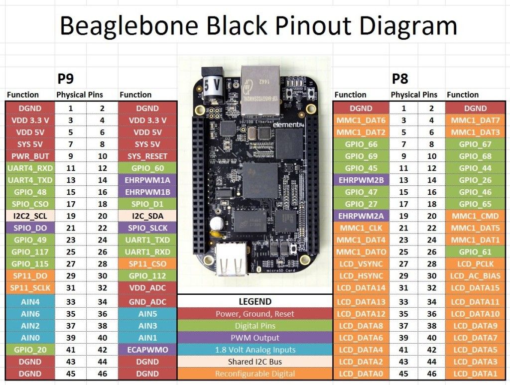
In my setup, BeagleBone acts as the I2C master, so it controls the clock and requests data from 0x30 and 0x34. It took me some time to figure out which I2C bus I should use, as my first app was listening to 0x34, but whenever I sent a message to the bus 0 with chip address 0x34, I did not get anything back.
My first suspect was my Arduino code and, after 2 hours of not getting anywhere, I tested bus 2 and everything worked. Later, I also found that bus 0 is not accessible via pins: Beaglebone Black I2C Tutorial | Microcontroller Tutorials
Wrong bus:
1 2 3 4 5 6 7 8 9 10 11 |
$ i2cdetect -yf 0 0 1 2 3 4 5 6 7 8 9 a b c d e f 00: 10: 20: 30: -- -- -- -- 34 -- -- -- 40: 50: UU -- -- -- -- -- -- -- -- -- -- -- -- -- -- -- 60: 70: |
And the correct one:
1 2 3 4 5 6 7 8 9 10 11 |
$ i2cdetect -yf 2 0 1 2 3 4 5 6 7 8 9 a b c d e f 00: 10: 20: 30: 30 -- -- -- 34 -- -- -- 40: 50: -- -- -- -- -- -- -- -- -- -- -- -- -- -- -- -- 60: 70: |
Standard Linux I2C tools to test
1 2 3 4 5 6 7 8 9 10 11 12 13 14 15 16 17 |
#!/bin/bash S1=0x30 S2=0x34 send(){ for msg in 0 1 2 3 do echo send $msg set LED to ${msg/2/ON} ${msg/[^2]/OFF} i2cset -f -y 2 ${1} ${msg} echo is LED disabled ? ask slave i2cget -f -y 2 ${1} sleep 1 done } send $S1 send $S2 |
And my bus scanner Python script:
1 2 3 4 5 6 7 8 9 10 11 12 13 14 15 16 |
# python 3 scan_i2c.py # pip3 install "--upgrade adafruit-blinka adafruit-platformdetect" import time import board i2c = board.I2C() while not i2c.try_lock(): pass try: while True: print("I2C addresses found:", [hex(device_address) for device_address in i2c.scan()]) time.sleep(2) |
So there you have it – a simple setup to start hardware hacking with I2C sniffing!
As the popularity of IoT devices continues to grow, hardware hacking can help IoT owners to understand their gadgets and improve device security. If you haven’t already, read our latest IoT botnet report and stay tuned for more insights from CUJO AI Labs: subscribe to our newsletter and follow CUJO AI Labs on Twitter.