
Building the IoTrain

While developing the Matter workshop for DEF CON, I wondered what fun IoT project I could create that looks catchy, works well with DEF CON visitors, and is within my capabilities. One day, while walking the baby stroller, I had an epiphany – building a Matter-controllable toy train.
About Matter
Matter is the new cool kid in town, the first application-level IoT protocol I can get excited about. Previously, you had to choose an ecosystem and stick to it. Wanted a smart home based on Apple HomeKit? Sorry, Android users. Samsung SmartThings? Sorry, Amazon Alexa fans.
Even worse, every IoT device had its own mobile app, and one had to figure out how to share control of the devices with the rest of the family. I got to a point, where I could not remember which app I had to use to control one of my IoT devices.
But thanks to Matter, this nightmare is over, and we have arrived in the promised land (terms and conditions apply).
Building the IoTrain
For the Matter workshop, I already had Raspberry Pis with blinking LEDs – but I wanted something more exciting. If you want to build the same Raspberry Pi environment, just follow these instructions.
My original idea for the Matter IoTrain was to control the train track via Matter, but after consulting someone in the hardcore model railroad world, they told me I could set this up in about three months, and it would cost me “only” around a thousand dollars. My original idea was to do it in one week for under ~40 bucks, so I had to look for some alternative solutions. I went to the nearest toy shop and bought this beauty for ~$25.
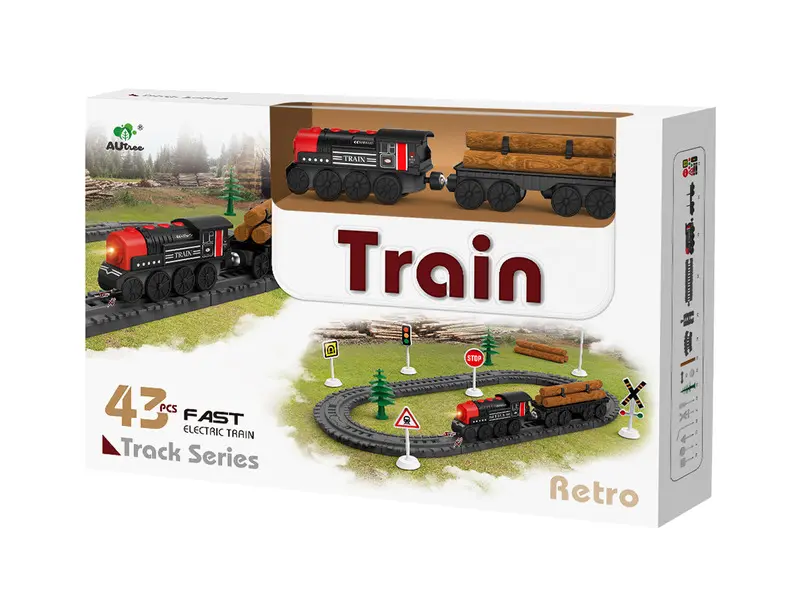
It was clear from the beginning that I wouldn’t be able to switch tracks, but at least I could start and stop the train via Matter. And that still counts, I guess.
The next piece of the puzzle was choosing a microcontroller. Since we had multiple ESP32-C3-DevkitM-1 in our lab, that seemed like a good option. Clearly, you can opt for a cheaper/smaller ESP32 option, but this was the microcontroller I had at hand.
I preferred using a Wi-Fi-based solution instead of Thread for the workshop, because it would be more complicated to commission a Thread device for users showing up with Linux laptops. And I did not want to hand out Thread dongles, like an nRF52840.
The next step was to design and build the IoTrain on a breadboard. I am a newbie when it comes to designing and building anything with a microcontroller. I know my solution is nowhere near perfect, but it got the job done. Luckily, the firmware part was easier than expected, since Espressif released their Zerocode platform. Zerocode was the perfect solution for me.
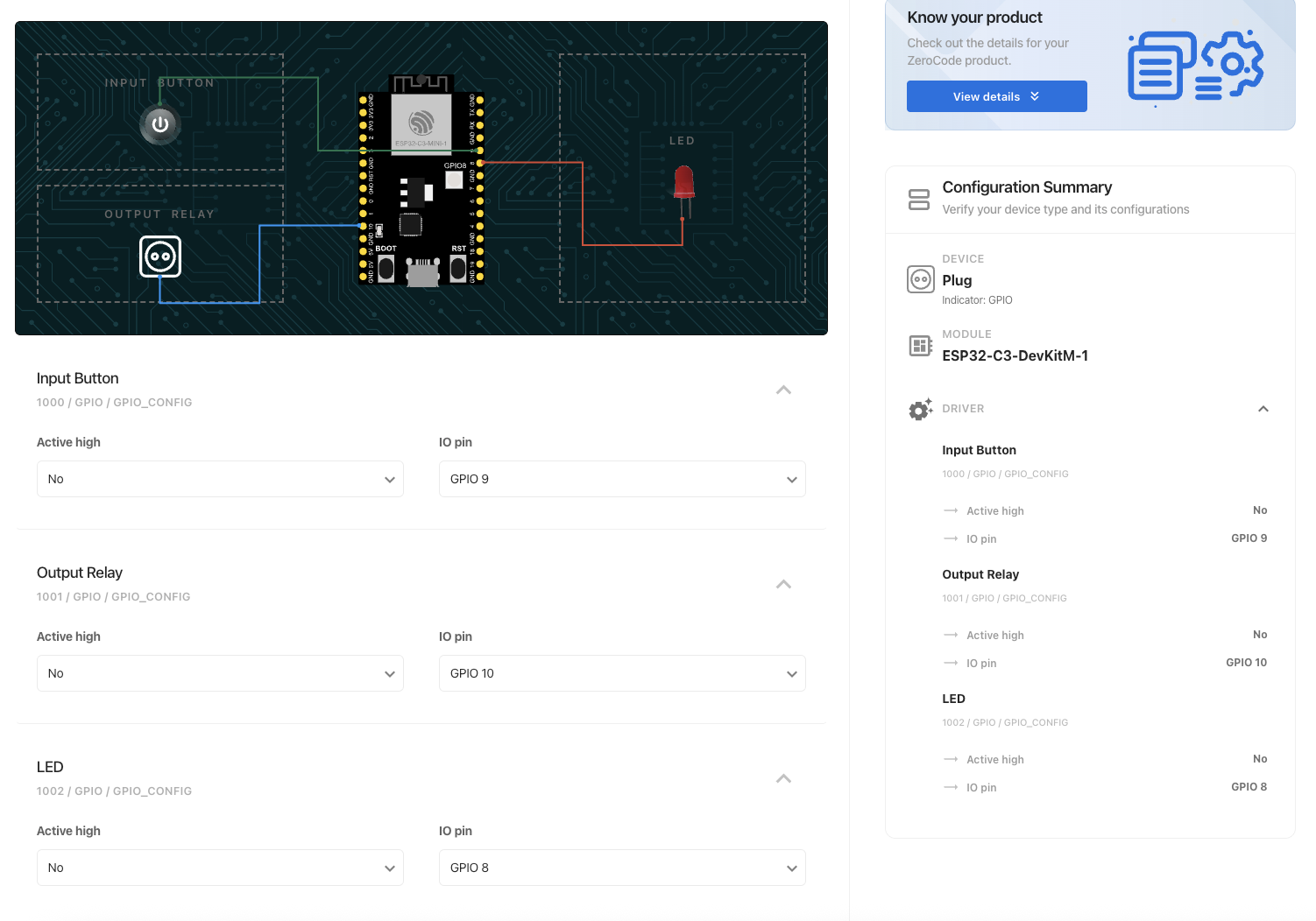
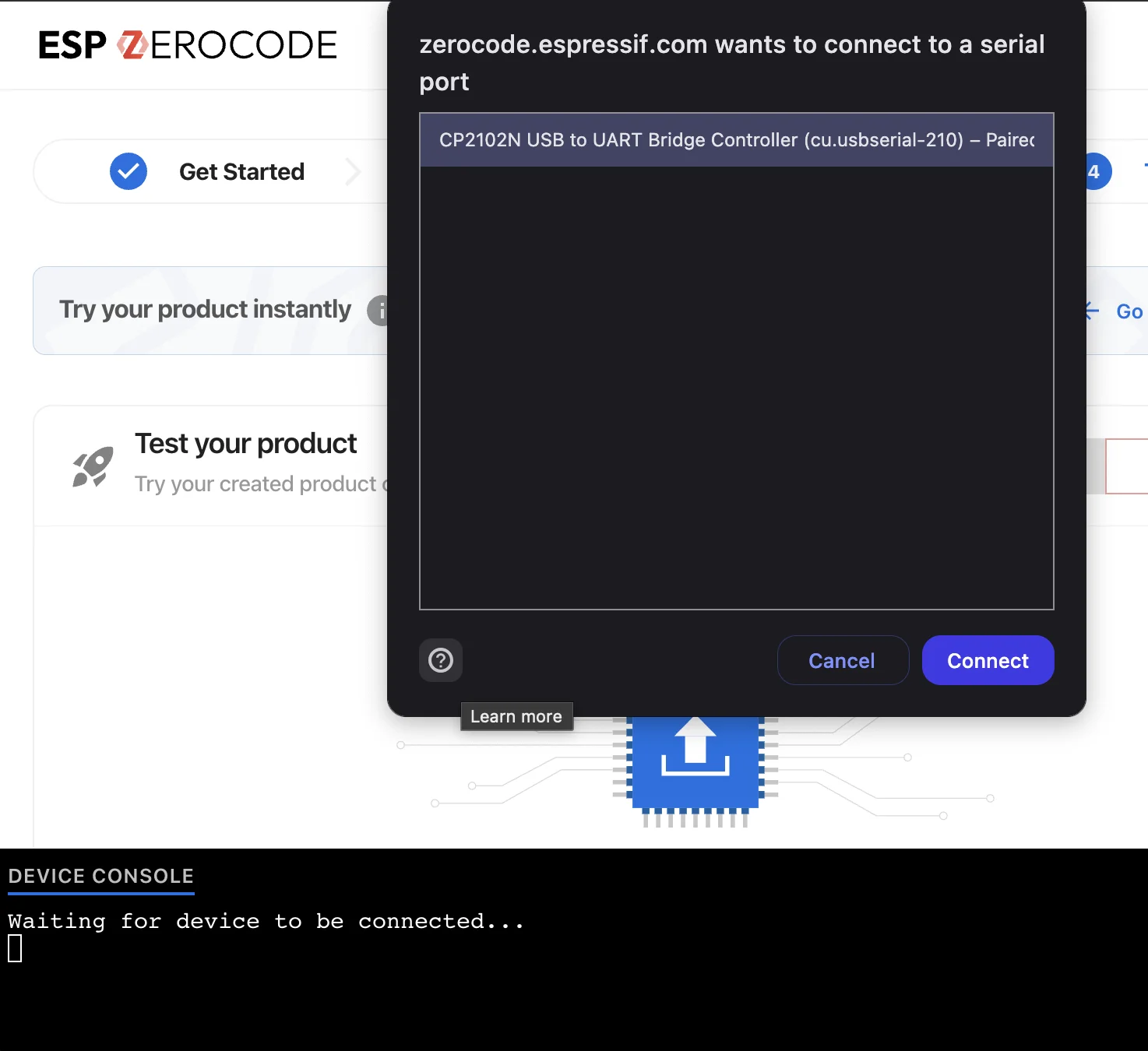
I had “challenges” with esp-idf and esp-matter in the past, and I was happy for not having to use those solutions manually. What I really love about ESP ZeroCode is that it uses WebUSB to flash the firmware onto the ESP32 – you don’t need to install any tools, just create the firmware and flash it from the web browser.
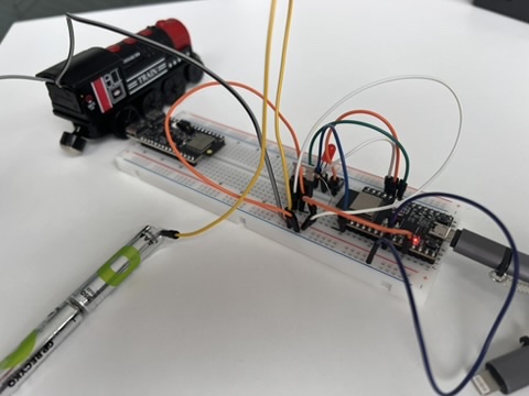
Now, with a working Matter-compatible microcontroller and zero circuit design skills, I came up with the following:
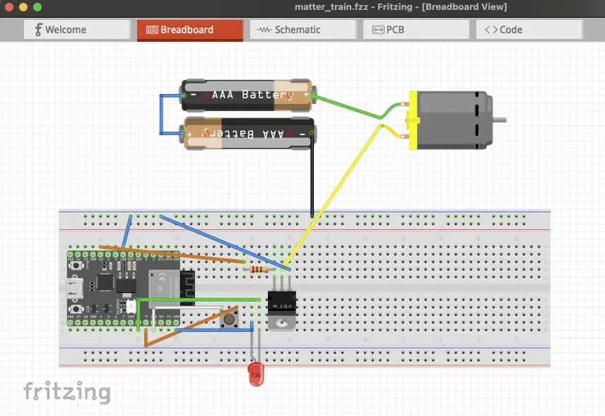
The top right motor component is the train, with its own battery source. Connecting the small button and the LED to the ESP32 is trivial (I probably should have used a resistor before the LED, but I was lazy). I chose the IRL540 MOSFET (bottom left) for controlling the battery connection to the train. If you are new to MOSFETs like me, you connect the MOSFET gate to the ESP32 output relay GPIO pin through a resistor (220 Ohm in my case), the MOSFET source should be connected to the common ground of the ESP32 and the batteries, and the MOSFET drain is connected to the negative terminal of the train.
For a proper design, you should add a flyback diode to the positive terminal of the load to protect the MOSFET, but ain’t nobody got time for that. The result was ugly, especially when I contacted the batteries with duck sellotape, and it kind of worked.
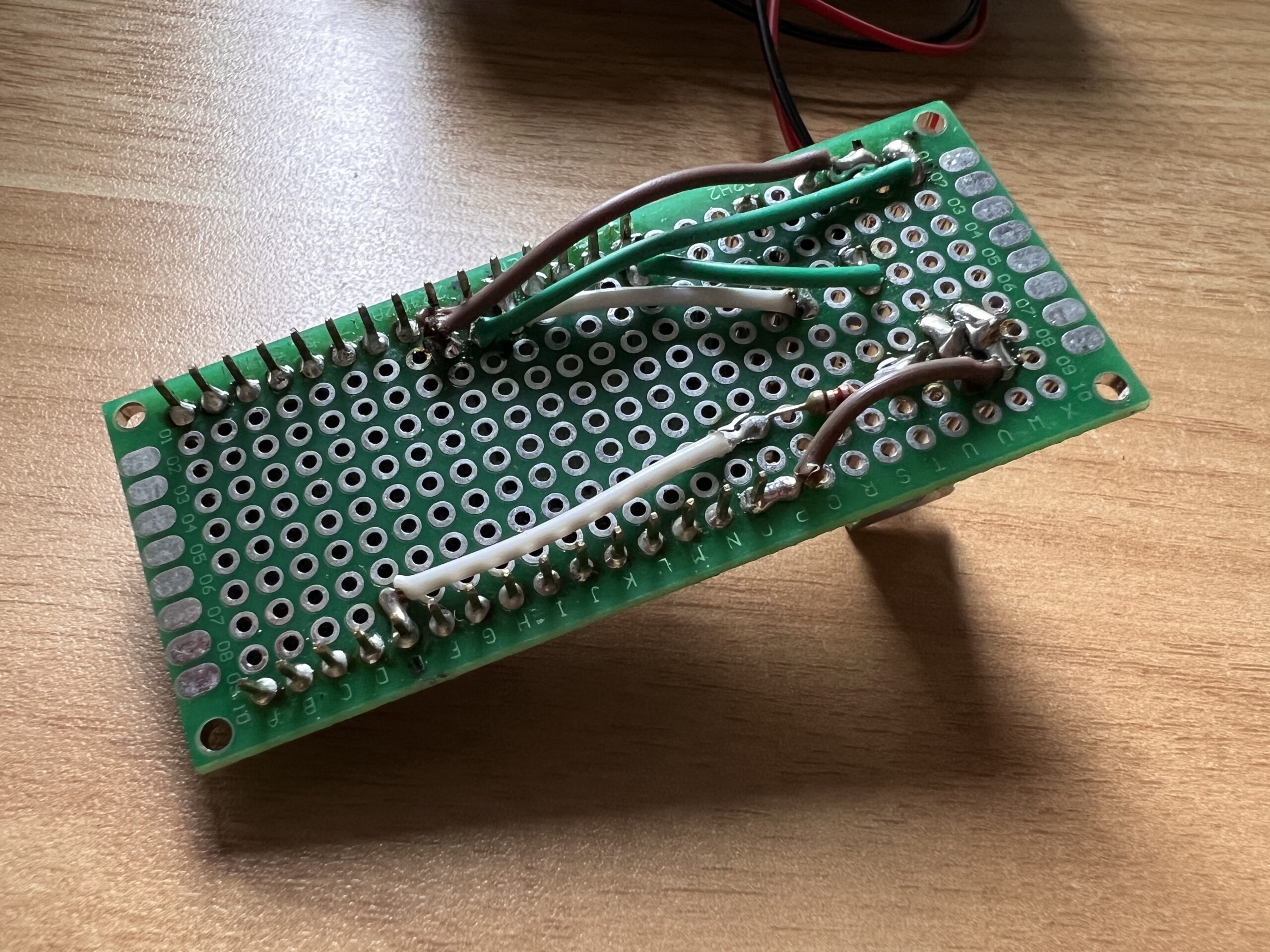
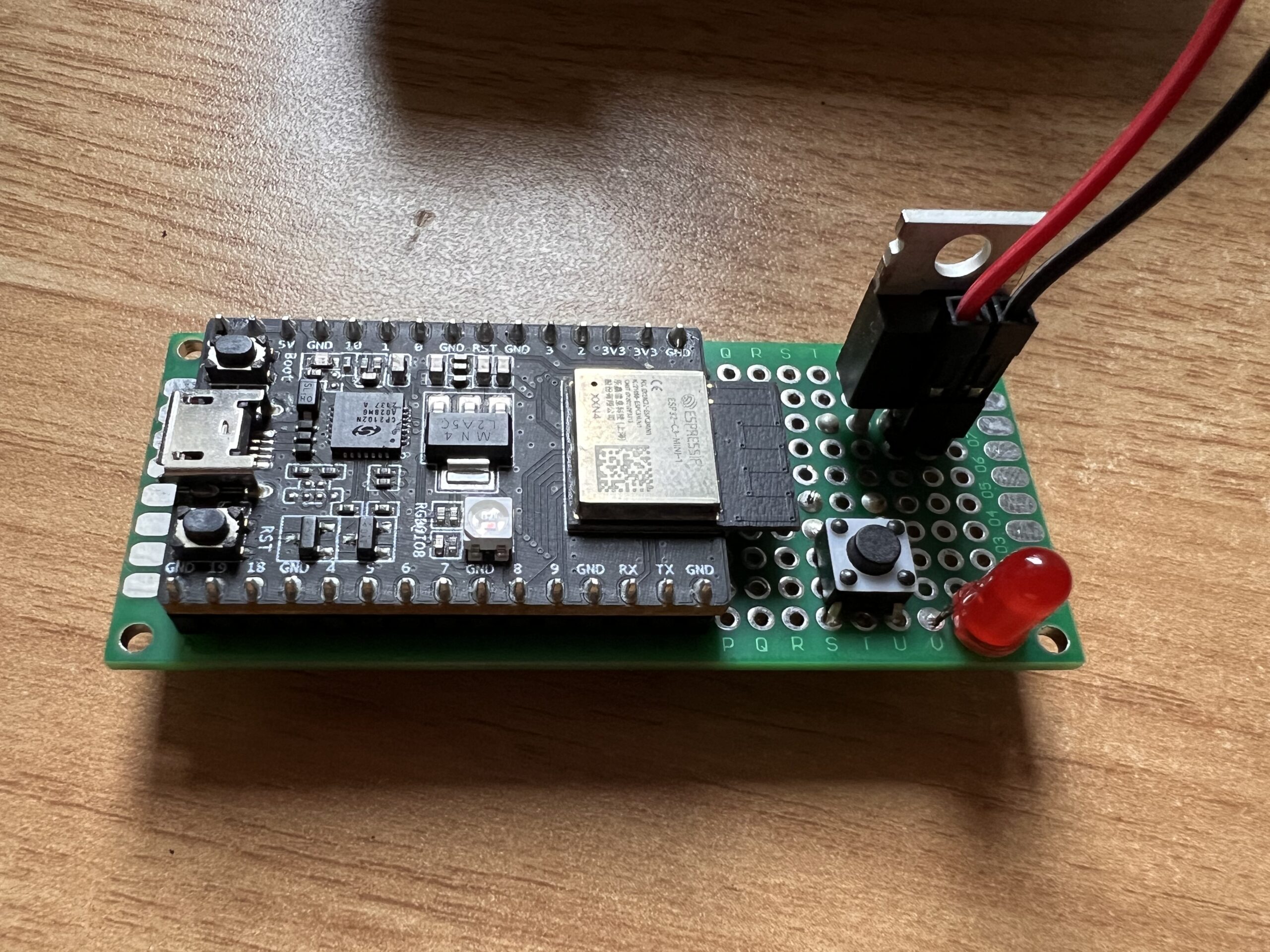
Now, it was time to upgrade this project to a proper proto PCB. Please don’t judge my soldering/wiring skills.
As for the power source for the ESP32, I found this USB power bank lying at home to be a perfect solution, as it nicely fitted into the second wagon of the train.
Unfortunately, when I ordered the second USB power bank, I did not expect domestic shipping to take four weeks… So I ended up with the following beautiful backup solution.
It is a 3V, CR123A battery taped to the proto PCB and connected to the 3.3V input of the ESP32. Don’t try this at home. You have been warned.
I tried multiple ways to interface with the train, and this one turned out to be the most stable.
I cut the gate connecting the two batteries together, drilled a hole into the back of the train, and connected these to the proto PCB.
And the end result?
See for yourself: